My doctoral research has become very “mixed-signal” in nature. Mixed-signal means there is a lot of interaction between digital and analog signals in a circuit. Even though I have access to state-of-the-art mixed signal simulators, these are expensive luxurious tools and there is no guarantee I will have access to them in the future. So I would like to create a free, open-source one! There are good open-source Spice and HDL (digital) simulator available, so what is needed is integration. This will happen in Python (a scripting programming language).
So how does a mixed-signal problem look like?
Case #1
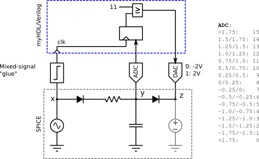
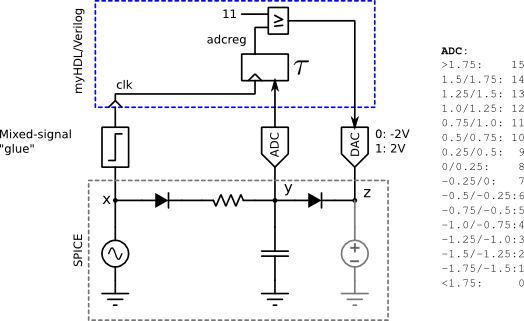
As you can see, there is an analog circuit (bottom), a digital circuit (top) and some “glue” logic that provides a bridge between the analog and digital parts. “Events” determine when each simulation, spice or HDL (digital), is paused, and equivalent values are converted from one domain to another.
In this circuit we have 3 different “glue” elements. The first is a comparator which looks at the analog value in a spice node and waits for it cross a threshold (V(x) > or < 0 Volts). This is the “event”. Then a logic ‘0’ or ‘1’ is set on the digital signal ‘clk’. The second is an ADC (Analog to digital converter) which simply reads the analog voltage at a node and converts is to a digital value. The “event” for this conversion is the rising edge of the ‘clk’ signal clocking the register that will hold the value of the ADC. Finally, a DAC (Digital to analog converter) translates a digital word into an analog voltage. The “event” when this happens is a change in the digital input to the DAC.
Notice the voltage source in gray on the far right. It is “paired” with the DAC to supply the voltage at the DAC to the analog circuit. It’s voltage is changed according the the value of the DAC.
The diagram below describes how a simulation would run:
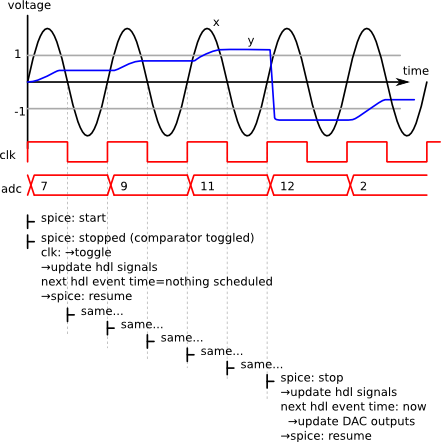
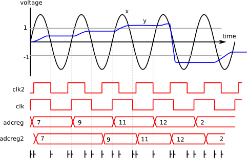
This is a relatively simple case because the only event is the transition of the comparator, when V(x) goes from negative to positive and vice versa. All updates, to the analog and digital circuits, occur when the spice simulation stops for this condition. Naturally, the clock (clk) is updated, the ADC register is updated because it is clocked by the same ‘clk’ signal, and so is the output of the DAC. No events are expected on the digital side until the comparator triggers again.
The following example illustrates the complexity that can arise when events are expected in the digital side before the spice simulator stops again.
Case #2
Consider this change in the digital circuit:
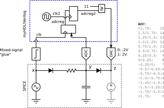
The register of the ADC is “re-timed” in a second register by a different clock (clk2). Situations like this are not uncommon.
Let’s look at how this would run:
The effect of the change is that there is some small delay and the capacitor is discharged a little later.
The simulation sequence gets complicated from the very beginning. Say we start the HDL simulation first. Then the first event would be the rising edge of ‘clk2′. After that, we start the spice simulator and realize that the rising edge of ‘clk’ happened earlier. Then we need to reset or re-run the HDL simulation from the beginning and stop at the time of the rising edge of ‘clk’ to compute it’s correct state before the rising edge of ‘clk2′ happens.
The penalty of re-simulating a small time interval of HDL might be small, but the provisions to reset the HDL simulation to an earlier state need be available, otherwise the simulation would have to run again from the beginning.
One might infer that the cause of this problem is the fact that there is a clock source in the spice circuit and another in the HDL circuit. One solution to this could be to define all independent “event sources” in just one of the two domains.
Case #3
The problem presented in Case #2 can still happen even if “event sources” are only present in the spice side. Consider the small modification to Case #1 where the ADC register has a small delay τ.
The waveforms look like this:
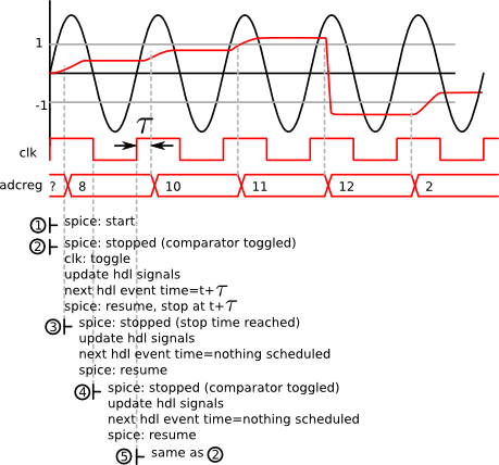
The spice simulation stops on the first rising edge of ‘clk’ (event 2) just as in the previous cases, but now we need to run the HDL simulation until the next event in order to know when the next event will happen (τ seconds later). This way we can resume the spice simulation and instruct it to stop at the time of the next event (event 3). Previously, we instructed the spice simulator to stop only when the comparator triggered. Now we are instructing it to stop at a specific time.
The problem here is that the comparator could toggle before the specified stop time. This would require an update of HDL signal, and potentially, the previously scheduled event might not even happen (or happen at a different time). So we need to discard the scheduled events, and run the HDL simulation again.
This has been a first approach to understanding the complexities in synchronizing analog and digital simulators for implementing a mixed-signal simulators. Comments are appreciated as well as any other contribution towards this project.