This is a collection of projects that I’ve completed throughout my education and career.
24 GHz Passive-Reflective Phase Shifter on CMOS
Date: 2013, Context: PhD. Thesis research.
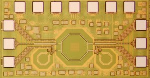
Description: Designed a millimeter-wave (24 GHz) phase shifter on CMOS. All-passive reflective-type. The variable phases is achieved through varactors. All components were designed using HFSS and the chip was designed using Cadence and Mentor tools.
Microstrip RF Filters
Date: 2013, Context: Microwave Design course project (GaTech).
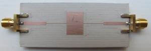
Description: A low-pass and a band-pass filters have been designed, simulated, implemented and measured. They have been implemented using Microstrip transmission lines on Rogers Duroid substrate.
Highlights: Scalable and efficient design methodology yielding a performance very close to calculations and simulations.
Discrete-component Colpitts VCO and FPGA based PLL
Date: 2012, Context: Oscillators and PLLs course project (GaTech).
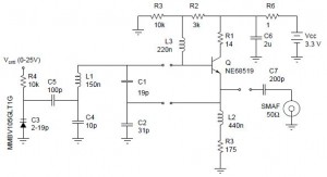
Description: 150 – 170 MHz Colpitts VCO built on a 2×2 square-square centimeter board, an Integer-N PLL implemented on an FPGA (See the Programmable Logic Development Platform project) with 1 MHz channel spacing, and a simple passive filter.
Highlights: Convenient control of the output frequency from a PC.
2-4 GHz and 4-12 GHz AWG Generator with CW input for the ALMA Observatory
Date: 2009, Context: Electronics Branch Lead for the ALMA observatory in the AIV division. Links: ALMA Observatory.
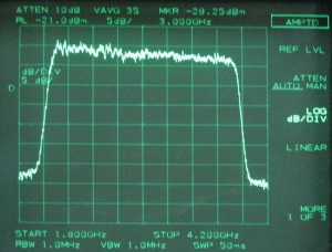
Description: Used to simulate the output of an ALMA radio-astronomy antenna front-end. White Gaussian noise generator with dual band outputs, 2-4GHz and 4-12GHz. Single input gets combined with the outputs. Digitally controlled step attenuator allows the control of output power for different scenarios. Remotely controlled through the ALMA real-time network using the “General Purpose Communication and Control Board for the ALMA Project” device described in this document.
Highlights: Very flat spectrum (Less than 3dB across 8 GHz). Thermally stable and robust.
Isolated Frequency Transmitter and Receiver for an Industrial Plant Telemetry
Date: 2008, Context: Independent Consultant.
Description: Devices of type A attached to paper cutting machines read the speed through rotary encoders or 4-20mA transducers and transmitted this value through differential signaling to a machine of type B, 100-200m away, which read (by time multiplexing) from several A-type devices and then transmit this information computer through RS-232. The whole system was optically-isolated for safety and robustness. Cannot provide further detail at this time.
Highlights: The whole system operates 24 hours every day of the year in a harsh environment and has not had any kind of malfunction for more than 14 months.
Media and Data diagnostics test appliance for the ALMA Project
Date: 2009, Context: Electronics Branch Lead for the ALMA observatory in the AIV division.
Description: The ALMA real-time communications bus comprises a CAN bus, a Time Event pulse, and a Reset line. All these are carried by shielded twisted pair cable with DB9 connectors. The test appliances is a portable, battery operated devices that tests: Signal integrity, traffic, common-mode voltage, Timing event presence and accuracy, termination resistance, and others. Base on a microcontroller with ADCs plus 3 differential transceivers, LCD display, and Li-Ion battery.
Highlights: Has reduced diagnostic time enormously by replacing a volt-meter, an oscilloscope with differential probes, connectors and adapters, and the time consuming setup and interpretation of results.
High Q Resonant Cavity Filter at 1.0 GHz
Date: 2009, Context: Personal research project.
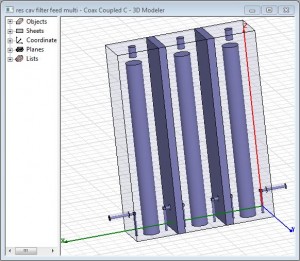
Description: 4-stage coaxial cavity resonator designed primarily by full 3D electromagnetic simulation using Ansoft HFSS.
Highlights: Q>500 (BW approx. 2MHz)
0-2.0 GHz Frequency Synthesizer
Date: 2009, Context: Personal research project.
Description: 1-2GHz synthesizer based on a reference CMOS oscillator fed to a DDS chip used as a steering reference for a PLL. This was mixed with a fixed frequency oscillator at 1GHz to provide a second output from 0 to 1GHz.
Highlights: -80dBc/Hz phase noise and -70dBc spurs. 2-3Hz tuning resolution across the whole range. Excellent cost-performance balance.
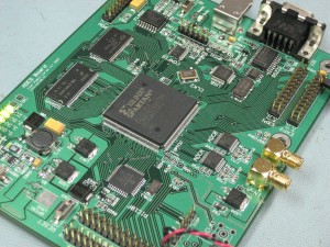
Programmable Logic Learning Platform
Date: 2008, Context: Engineering Degree Thesis
Description: General purpose board with an FPGA as primary component plus a microcontroller, DRAM, SDRAM, Flash, 2-100 Msps ADC, RS-232, USB, and switching power supply. Built on a 4 layer PCB. Main focus and research was digital signal integrity, which includes high performance PCB design through design rules and verification through electromagnetic and IC I/O performance simulation. Developed several examples in VHDL to test all functionality and performance.
Highlights: Very large design was fully functional and delivered good performance after one iteration. This thesis gained the author the Electrical Engineering Degree with Highest Honors. Faculty proposed the creation of a graduate level course on digital design using the written thesis as lecture material and the development board for laboratory exercises.
Broken Coil detectors in Conveyor belts
Date: 2006, Context: Advanced Electronics course project. Links: Article in EDN Magazine.
Description: Fully analog circuit detects broken coils embedded in mining conveyor belts. The inductor of an LC oscillator is coupled with the passing coils. A broken coil causes a change in frequency which is detected by the simplest FM demodulator. A timing circuit is included to account for the time between coils. Ready to interface with controller to alert the operator or tell the location of the broken coil.
Highlights: Fully analog design using only general purpose op-amps, BJTs, diodes, resistors, capacitors and inductors.
M&M Sorting Machine
Date: 2005, Context: Mechatronic Design Graduate Workshop at Carnegie Mellon University.
Description: Teamed up with one Mechanical Engineer and one Industrial Designer to build that year’s project and compete with the rest of the class. We chose to compete by the speed parameter (M&Ms sorted per second). The machine consisted on a rotary slotted wheel which turned over 4 buckets (for three different colors and the rest). The M&Ms were delivered into a slot by a vibrating funnel, and servo-actuated gates opened below the slots to allow the M&M of the right color to drop into each of the buckets. The electronics did the color sensing, speed control of the wheel, opening of the gates, and logic to control the opening of the gates at the right time for the right color.
Highlights: Sorted 3+ M&M per second with accuracy above 90%. Excellent multidisciplinary team work.
Isolated Dimmer with digital control
Date: 2006, Context: Teaching Assistant for the Circuits Laboratory Course
Description: Fully isolated, optically coupled single-phase half-wave dimmer. One port is the output for the zero crossing detector and a second port to trigger a power SCR. Can be easily expanded to handle full-wave. Can be controlled from a Cpu or a 555 timer.
Highlights: Compact, robust, safe, minimum number of components.
PC-interfaced Digital Sampling Oscilloscope
Date: 2006, Context: Electronic Design Course Project.
Description: Fully standard and configurable from a personal computer. 2 channels have 10MHz BW and are sampled at 40 Msps simultaneously. 1, 2, 5-type vertical and horizontal scales. Direct or DC blocked input. 1024 sample memory. Digital slope and voltage configurable trigger with configurable pre- and post-trigger capture lengths. Serial interface communications and demonstration software written in Matlab. Capture engine handled by a CPLD with firmware written in VHDL and high level control and communications handled by a microcontroller with firmware written in C.
Highlights: Best semester project. Fully self contained. Simple instruction set. Fully configurable.
Analog Data Acquisition and Generation for PC-based pseudo-real-time control
Date: 2004, Context: Control Systems Laboratory Course project.
Description: Simple USB interface board for the generation and measurement of analog signals with close to real-time performance. Designed for the laboratory course students to control physical devices by writing their own code in a PC running either Linux or Windows. Analog output was implemented using an R2R ladder and the analog input using the built-in ADC of a microcontroller.
Highlights: About 1 KHz update rate with enough free CPU time for an on-board PID controller using floating point numbers, or for data communication with the host PC between updates.
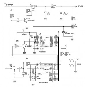
Step-Down Buck Converter
Date: 2003, Context: Digital Systems Laboratory Course project.
Description: DC-DC Converter in Buck configuration with PID control of the output voltage with a tiny micro-controller. Wide input and output range: Vin from Vout to 40V, Vout from 1.5V to Vin, all at 10A or less.
Highlights: Digital and Power Electronics integration. Compact and robust. Tested with large load variations and driving DC motors.
// JPC


