The video below shows no magic. It’s a simple and beautiful example of engineering.
Making a piece of metal float in the air is the combination of the understanding and clever manipulation of basic forces of nature to accurately produce desired results. This is probably a general description of what engineering is all about. This particular example has always amazed me though, because it seems to defy nature, it combines several engineering disciplines, and at the same time, is relatively simple. Show this to someone thinking of becoming an engineer!
So let me explain it. The big picture first. The sub-discipline of electrical engineering that deals with “keeping or putting things where you want them” is called Control Systems. The simplest example is the temperature control of your heating/cooling system at home. You set your desired temperature and the thermostat looks a the current temperature. The difference is the “error”. It is used to decide what to do. If it is positive (the desired temperature is higher than the actual), it turns on the heating. If it is negative, the it turns it off. This keeps the temperature where you want it.
For the magnetic levitator the situation is similar. The setting is the desired position of the suspended mass. The controller looks at the current position to compute the position error. If the mass is too low, it increases the force on the electromagnet above, otherwise, it decreases it.
The figure below shows a diagram of the system:
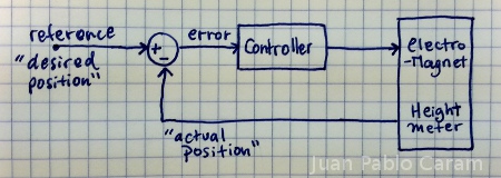
Boxes and arrows are the alphabet of electrical (and other) engineers. So what you see above is an explanation of the magnetic levitator in electrical engineering language. The arrows are signals. Signals are some quantity, magnitude, or intensity. The boxes are operations, which receive signals, do something with them, and output new ones.
“Desired position” and “actual position” are signals of the same kind, height of the levitated object”m so we can carry out a subtraction operation, represented by the circle with “+” and “-” symbols. The “error” is the result of the operation. It is the input to “Controller”, whose task is to set the intensity of the electromagnet in such a way that the object levitates, or that the “error” becomes zero (or constant right?)
The operation done by the “Controller” to establish the intensity of the electromagnet based on the error is quite simple, but perhaps too advanced to be relevant to this writing. The point is that the operation is just well known math at the calculus level.
So the question that probably remains is what are the signals and operations made of? My answer is that it doesn’t really matter much (up to certain point, to the control systems engineer). He can design and test this on the computer. But if we want to build it we need to explore some other areas in electrical engineering. Keep in mind that certain parts of the levitator could be implemented as a program on a computer, but let’s assume we want to completely build it with analog circuits. The analog circuit designed (a specialized electrical engineer) uses operational amplifiers to do math. Operational amplifiers are one of the oldest and most used circuits ever. So the “operation” boxes are made with one or more operational amplifiers. The signals are typically voltages or currents (stuff that moves on wires.) Conveniently, the arrow and boxes in the drawings resemble the real thing in circuits, this is, wires and chips!
What you see in the video too me and a friend just a couple of hours to build (after knowing what parts we would need and making sure we had them ready.) It required almost no math at all. It is not that complicated. After this, you can go after much harder tasks… google “Inverted pendulum” and watch some videos.
Control Systems is what is behind the autopilot in a passenger jet, what keeps a “segway” standing despite having only two wheels, and what keeps many things running smoothly and safely without you ever noticing. I hope this writing serves as some inspiration!